

Getting start
User manual
Accessories
The standard set of AIO-PX30-JD4 includes the following accessories:
- Core-PX30-JD4 main board ×1
- MB-JD4-RK3328&PX30 base board ×1
- Brass antenna ×1
- 12V-2A Power adapter ×1
- Type-A to Type-C data cable ×1
Other optional accessories:
- Firefly Serial Module
In addition, you may need the following accessories during use:
- Display device
- 10.1 inch LVDS screen
- Network
- 100M Ethernet cable, and wired router
- WiFi router
- Input devices
- USB wire/wireless mouse/keyboard
- Infrared remote control (need to connect to the infrared receiver)
- Firmware upgrade and debugging
- Type-A to Type-C data cable
- Serial port to USB adapter
Firmware type
Firmware comes in two formats:
- Raw firmware
- RK firmware(Rockchip firmware)
Raw firmware is a firmware that can be upgraded to a storage device in a bit-by-bit replication mode. It is the original image of the storage device. Raw firmware is generally upgraded to an SD card, but it can also be upgraded to an eMMC. There are many tools available to upgrade the original firmware:
RK firmware is a firmware packaged in Rockchip proprietary format and upgraded to eMMC flash memory using upgrade_tool(Linux) or AndroidTool(Windows) tools provided by Rockchip. RK firmware is Rockchip's traditional firmware packaging format and is often used on Android devices. In addition, Android's RK Firmware can be upgraded to an SD card using the SD Firmware Tool.
Partition image is the image data of a partition and is used to store the upgrade of the corresponding partition of the device. For example, the compilation of the Android SDK will construct boot.img, kernel.img and system.img etc. Partition image file ,the kernel.img will be written in eMMC or SD card "the kernel" partition.
Download and update firmware
The following is a list of supported systems:
- Android 8.1
- Ubuntu 18.04
Choose the right tool to upgrade the firmware according to the operating system used:
- upgrade to SD
- upgrade to eMMC
- Graphical interface upgrade tool:
- AndroidTool (Windows)
- Command line upgrade tool:
- upgrade_tool (Linux)
- Graphical interface upgrade tool:
Boot
After confirming the correct connection of motherboard accessories, insert the power adapter into a live socket and the power line interface into the development board. The development board will automatically start up after the first power on. When the machine is turned on, the blue power indicator light will be on. If the board is connected to the LVDS monitor, you can see the official logo of Firefly.
Senial debug
Buy Adapter
There are many USB adapter to serial port on the shop, divided by chip, there are the following:
- CP2104
- PL2303
- CH340
Hardware Connection
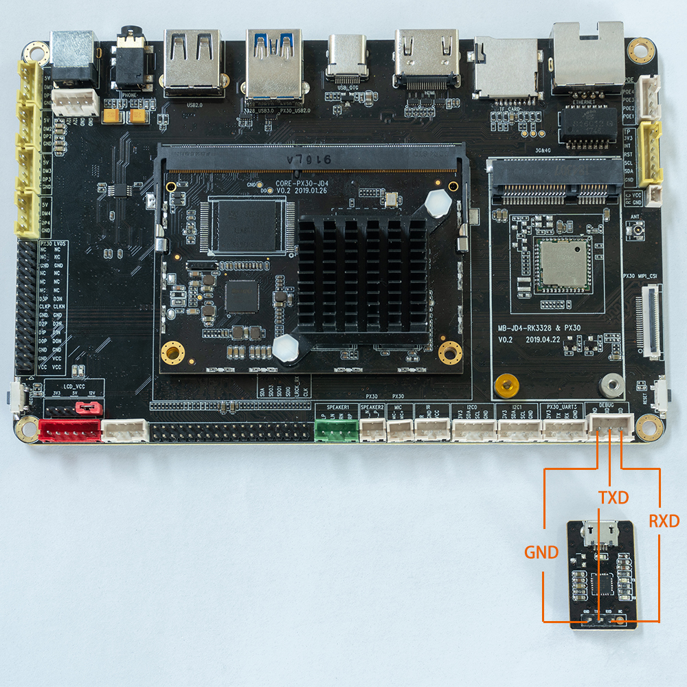
Serial port to USB adapter, there are four pins:
- 3.3V Power, no need to connect.
- GND,Ground, connect to GND pin of the board.
- TXD,Transmit,connect to TX pin of the board.
- RXD,Receive, connect to RX pin of the board.
Note: If you encounter the problem that TX and RX cannot input and output when using other serial adapters, you can try to exchange TX and RX connections.
AIO-PX30-JD4 serial port connection diagram:
Parameter Setting
AIO-PX30-JD4 use the following serial parameters:
- Baud rate: 1500000
- Data bit: 8
- Stop bit: 1
- Parity check: none
- Flow control: none
Use serial on Windows
Install Driver
Download driver and install:
After the adapter is inserted, the system will prompt for the discovery of new hardware and initialization, and then the corresponding COM port can be found in the device manager:
Install Software
Putty or SecureCRT are commonly used for Windows. Putty is open source software and SecureCRT is used in a similar way. Here to Download putty. (Recommended download putty.zip, it contains other useful tools.)
Extract and run PUTTY.exe.
- Select
Connection typetoSerial. - Modify
Serial lineto the COM port found in the device manager. - Set
Speedto 1500000. - Click
Openbutton.
Use serial debug on Ubuntu
There are many options available on Ubuntu:
- minicom
- picocom
- kermit
The following shows how to use minicom.
Install minicom
sudo apt-get install minicomTo connect the serial port line, see what the serial port device file is. The following example is /dev/ttyusb0:
$ ls /dev/ttyUSB*
/dev/ttyUSB0
Run:
$ sudo minicom
Welcome to minicom 2.7
OPTIONS: I18n
Compiled on Jan  1 2014, 17:13:19.
Port /dev/ttyUSB0, 15:57:00
Press CTRL-A Z for help on special keys
Based on the above tips: Press Ctrl-a and then press Z again to bring up the help menu.
+-------------------------------------------------------------------+
|                      Minicom Command Summary                      |
|                                                                   |
|              Commands can be called by CTRL-A                     |
|                                                                   |
|               Main Functions                  Other Functions     |
|                                                                   |
| Dialing directory..D  run script (Go)....G | Clear Screen.......C |
| Send files.........S  Receive files......R | cOnfigure Minicom..O |
| comm Parameters....P  Add linefeed.......A | Suspend minicom....J |
| Capture on/off.....L  Hangup.............H | eXit and reset.....X |
| send break.........F  initialize Modem...M | Quit with no reset.Q |
| Terminal settings..T  run Kermit.........K | Cursor key mode....I |
| lineWrap on/off....W  local Echo on/off..E | Help screen........Z |
| Paste file.........Y  Timestamp toggle...N | scroll Back........B |
| Add Carriage Ret...U                                              |
|                                                                   |
|             Select function or press Enter for none.              |
+-------------------------------------------------------------------+
Press O to enter the setting interface, as follows:
           +-----[configuration]------+
           | Filenames and paths      |
           | File transfer protocols  |
           | Serial port setup        |
           | Modem and dialing        |
           | Screen and keyboard      |
           | Save setup as dfl        |
           | Save setup as..          |
           | Exit                     |
           +--------------------------+
Move the cursor to Serial port setup, press enter to enter the Serial port setup interface, then enter the letter prompted earlier, select the corresponding option, and set it as follows:
  +-----------------------------------------------------------------------+
   | A -    Serial Device      : /dev/ttyUSB0                              |
   | B - Lockfile Location     : /var/lock                                 |
   | C -   Callin Program      :                                           |
   | D -  Callout Program      :                                           |
   | E -    Bps/Par/Bits       : 1500000 8N1                               |
   | F - Hardware Flow Control : No                                        |
   | G - Software Flow Control : No                                        |
   |                                                                       |
   |    Change which setting?                                              |
+-----------------------------------------------------------------------+Hardware Flow Control and Software Flow Control should be set to No, otherwise it may not be impossible to input.
After finishing the setting, go back to the previous menu and select Save setup as dfl to save as the default configuration, which will be used by default later.