

Camera
MIPI CSI
RK3566/RK3568 platform only has one physical mipi csi2 dphy, it can work in two modes: full mode and split mode; and split into three logical dphy: csi2_dphy0, csi2_dphy1, csi2_dphy2 (See detail in rk3568.dtsi)
Full Mode
- Only use csi2_dphy0 (csi2_dphy0 and csi2_dphy1/csi2_dphy2 cannot be used at the same time);
- Maximum 4 data lanes;
- Maximum speed 2.5Gbps/lane;
Split Mode
- Use csi2_dphy1 and/or csi2_dphy2, cannot use csi2_dphy0 at this mode;
- csi2_dphy1 and csi2_dphy2 can be used at the same time;
- csi2_dphy1 and csi2_dphy2 both have maximum 2 data lanes;
- csi2_dphy1 maps to physical dphy lane0/lane1;
- csi2_dphy2 maps to physical dphy lane2/lane3;
- Maximum speed 2.5Gbps/lane
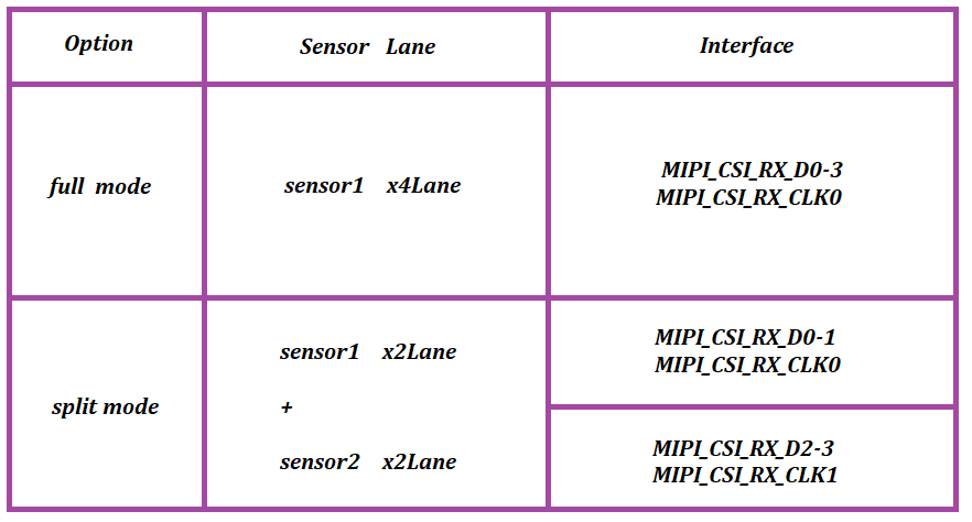
In short, if we use single-camera, we can set dphy to full mode, if we use dual-camera, we can set dphy to split mode.
Full Mode Configuration
Link path: sensor->csi2_dphy0->isp
Full Mode DTS Configuration Key Points
Configure Sensor
We need to check the MIPI CSI interface in schematic to find out which I2C bus is used for camera sensor. And configure the camera under that I2C node, correctly set the properties like I2C device address, pins, etc. For example, there's a configuration for xc7160 in ROC-RK3566-PC:
&i2c4 {
        status = "okay";
        XC7160: XC7160b@1b{
                status = "okay";
                compatible = "firefly,xc7160";
                reg = <0x1b>;
                clocks = <&cru CLK_CIF_OUT>;
                clock-names = "xvclk";
                power-domains = <&power RK3568_PD_VI>;
                pinctrl-names = "default";
                pinctrl-0 = <&cif_clk>;
        	power-gpios = <&gpio4 RK_PB6 GPIO_ACTIVE_LOW>;
        	reset-gpios = <&gpio4 RK_PB0 GPIO_ACTIVE_HIGH>;
       		pwdn-gpios = <&gpio4 RK_PB7 GPIO_ACTIVE_HIGH>;
                firefly,clkout-enabled-index = <0>;
                rockchip,camera-module-index = <0>;
                rockchip,camera-module-facing = "back";
                rockchip,camera-module-name = "NC";
                rockchip,camera-module-lens-name = "NC";
                port {
                        xc7160_out: endpoint {
                                remote-endpoint = <&mipi_in_ucam4>;
                                data-lanes = <1 2 3 4>;
                        };
                };
        };
};
Configure Logical Dphy
csi2_dphy0 and csi2_dphy1/csi2_dphy2 cannot be used at the same time. In addition, we need to enable csi2_dphy_hw node.
&csi2_dphy0 {
        status = "okay";
        /*
        * dphy0 only used for full mode,
        * full mode and split mode are mutually exclusive
        */
        ports {
                #address-cells = <1>;
                #size-cells = <0>;
                port@0 {
                        reg = <0>;
                        #address-cells = <1>;
                        #size-cells = <0>;
...
                        mipi_in_ucam4: endpoint@5 {
                                reg = <5>;
                                remote-endpoint = <&xc7160_out>;
                                data-lanes = <1 2 3 4>;
                        };
                };
                port@1 {
                        reg = <1>;
                        #address-cells = <1>;
                        #size-cells = <0>;

                        csidphy_out: endpoint@0 {
                                reg = <0>;
                                remote-endpoint = <&isp0_in>;
                        };
                };
        };
};

&csi2_dphy_hw {
   status = "okay";
};

&csi2_dphy1 {
        status = "disabled";
};

&csi2_dphy2 {
        status = "disabled";
};
Configure Isp
The remote-endpoint in rkisp_vir0 node should point to csidphy_out
&rkisp {
   status = "okay";
};

&rkisp_mmu {
   status = "okay";
};

&rkisp_vir0 {
   status = "okay";
   port {
      #address-cells = <1>;
      #size-cells = <0>;

      isp0_in: endpoint@0 {
         reg = <0>;
         remote-endpoint = <&csidphy_out>;
      };
   };
};
Split Mode Configuration
Link path:
sensor1->csi_dphy1->isp_vir0
sensor2->csi_dphy2->mipi_csi2->vicap->isp_vir1
Split Mode DTS Configuration Key Points
Configure Sensor
We need to check the MIPI CSI interface in schematic to find out which I2C bus is used for camera sensor. And configure the camera under that I2C node, correctly set the properties like I2C device address, pins, etc. For example, there's a configuration for gc2053/gc2093 in ROC-RK3566-PC:
&i2c4 {
            status = "okay";
           gc2053: gc2053@37 { //IR
                status = "okay";
                compatible = "galaxycore,gc2053";
                reg = <0x37>;

                avdd-supply = <&vcc_camera>;
                power-domains = <&power RK3568_PD_VI>;
                clock-names = "xvclk";
                pinctrl-names = "default";
        	clocks = <&cru CLK_CAM0_OUT>;
        	pinctrl-0 = <&cam_clkout0>;
        	power-gpios = <&gpio4 RK_PB0 GPIO_ACTIVE_HIGH>;//IR_PWR_EN
        	pwdn-gpios = <&gpio4 RK_PB6 GPIO_ACTIVE_LOW>;
                firefly,clkout-enabled-index = <1>;
                rockchip,camera-module-index = <0>;
                rockchip,camera-module-facing = "back";
                rockchip,camera-module-name = "YT-RV1109-2-V1";
                rockchip,camera-module-lens-name = "40IR-2MP-F20";
                port {
                        gc2053_out: endpoint {
                                        remote-endpoint = <&dphy1_in>;
                                        data-lanes = <1 2>;
                        };
                };
        };
        gc2093: gc2093b@7e{ //RGB
                status = "okay";
                compatible = "galaxycore,gc2093";
                reg = <0x7e>;

                avdd-supply = <&vcc_camera>;
                power-domains = <&power RK3568_PD_VI>;
                clock-names = "xvclk";
                pinctrl-names = "default";
                flash-leds = <&flash_led>;
		pwdn-gpios = <&gpio4 RK_PB7 GPIO_ACTIVE_HIGH>;
                firefly,clkout-enabled-index = <0>;
                rockchip,camera-module-index = <1>;
                rockchip,camera-module-facing = "front";
                rockchip,camera-module-name = "YT-RV1109-2-V1";
                rockchip,camera-module-lens-name = "40IR-2MP-F20";
                port {
                        gc2093_out: endpoint {
                                        remote-endpoint = <&dphy2_in>;
                                        data-lanes = <1 2>;
                        };
                };
        };

};
Configure csi2_dphy1/csi2_dphy2
csi2_dphy0 and csi2_dphy1/csi2_dphy2 cannot be used at the same time.
&csi2_dphy0 {
         status = "disabled";
};

&csi2_dphy1 {
        status = "okay";
        /*
        * dphy1 only used for split mode,
        * can be used  concurrently  with dphy2
        * full mode and split mode are mutually exclusive
        */
        ports {
                #address-cells = <1>;
                #size-cells = <0>;

                port@0 {
                        reg = <0>;
                        #address-cells = <1>;
                        #size-cells = <0>;

                        dphy1_in: endpoint@1 {
                                        reg = <1>;
                                        remote-endpoint = <&gc2053_out>;
                                        data-lanes = <1 2>;
                        };
                };

                port@1 {
                        reg = <1>;
                        #address-cells = <1>;
                        #size-cells = <0>;

                        dphy1_out: endpoint@1 {
                                        reg = <1>;
                                        remote-endpoint = <&isp0_in>;
                        };
                };
        };
};

&csi2_dphy2 {
        status = "okay";
        /*
        * dphy2 only used for split mode,
        * can be used  concurrently  with dphy1
        * full mode and split mode are mutually exclusive
        */
        ports {
                #address-cells = <1>;
                #size-cells = <0>;

                port@0 {
                        reg = <0>;
                        #address-cells = <1>;
                        #size-cells = <0>;

                        dphy2_in: endpoint@1 {
                                        reg = <1>;
                                        remote-endpoint = <&gc2093_out>;
                                        data-lanes = <1 2>;
                        };
                };

                port@1 {
                        reg = <1>;
                        #address-cells = <1>;
                        #size-cells = <0>;

                        dphy2_out: endpoint@1 {
                                        reg = <1>;
                                        remote-endpoint = <&mipi_csi2_input>;
                        };
                };
        };
};

&csi2_dphy_hw {
      status = "okay";
};

&mipi_csi2 {
        status = "okay";

        ports {
                #address-cells = <1>;
                #size-cells = <0>;

                port@0 {
                        reg = <0>;
                        #address-cells = <1>;
                        #size-cells = <0>;

                        mipi_csi2_input: endpoint@1 {
                                        reg = <1>;
                                        remote-endpoint = <&dphy2_out>;
                                        data-lanes = <1 2>;
                        };
                };

                port@1 {
                        reg = <1>;
                        #address-cells = <1>;
                        #size-cells = <0>;

                        mipi_csi2_output: endpoint@0 {
                                        reg = <0>;
                                        remote-endpoint = <&cif_mipi_in>;
                                        data-lanes = <1 2>;
                        };
                };
        };
};


&rkcif_mipi_lvds {
        status = "okay";
        port {
                cif_mipi_in: endpoint {
                        remote-endpoint = <&mipi_csi2_output>;
                        data-lanes = <1 2>;
                };
        };
};

&rkcif_mipi_lvds_sditf {
        status = "okay";
        port {
                mipi_lvds_sditf: endpoint {
                        remote-endpoint = <&isp1_in>;
                        data-lanes = <1 2>;
                };
        };
};
Configure Isp
The remote-endpoint in rkisp_vir0 node should point to dphy1_out
&rkisp {
        status = "okay";
};

&rkisp_mmu {
        status = "okay";
};

&rkisp_vir0 {
        status = "okay";
        port {
                #address-cells = <1>;
                #size-cells = <0>;

                isp0_in: endpoint@0 {
                        reg = <0>;
                        remote-endpoint = <&dphy1_out>;
                };
        };
};

&rkisp_vir1 {
        status = "okay";

        port {
                reg = <0>;
                #address-cells = <1>;
                #size-cells = <0>;

                isp1_in: endpoint@0 {
                        reg = <0>;
                        remote-endpoint = <&mipi_lvds_sditf>;
                };
        };
};


&rkcif_mmu {
    status = "okay";
};

&rkcif {
    status = "okay";
};
Related Directory
Linux Kernel-4.19
|-- arch/arm/boot/dts #DTS configuration file
|-- drivers/phy/rockchip
|-- phy-rockchip-mipi-rx.c #mipi dphy driver
|-- phy-rockchip-csi2-dphy-common.h
|-- phy-rockchip-csi2-dphy-hw.c
|-- phy-rockchip-csi2-dphy.c
|-- drivers/media
|-- platform/rockchip/cif #RKCIF driver
|-- platform/rockchip/isp #RKISP driver
|-- dev #includes probe, asynchronous register clock, pipeline, iommu and media/v4l2 framework
|-- capture #includes mp/sp/rawwr configuration and vb2, frame interrupt handle
|-- dmarx #includes rawrd configuration and vb2, frame interrupt handle
|-- isp_params #3A-related parameters
|-- isp_stats #3A-related statistics
|-- isp_mipi_luma #mipi luminance data statistics
|-- regs #register-related read/write operation
|-- rkisp #isp subdev and entity register
|-- csi #csi subdev and mipi configuration
|-- bridge #bridge subdev,isp and ispp interaction bridge
|-- platform/rockchip/ispp #rkispp driver
|-- dev #includes probe, asynchronous register, clock, pipeline, iommu and media/v4l2 framework
|-- stream #includes 4-channel video output configuration and  vb2, frame interrupt handle
|-- rkispp #ispp subdev and entity register
|-- params #TNR/NR/SHP/FEC/ORB parameters
|-- stats #ORB statistics
|-- i2
Single Camera CAM-8MS1M/Dual Camera CAM-2MS2MF
Firefly has already configured these cameras in dts, CAM-8MS1M and CAM-2MS2MF cannot be used at the same time. Only need to include specific dtsi file to use CAM-8MS1M or CAM-2MS2M.
Linux already has dts and mk files of different matches, select before build, no need to modify files.
Android needs following changes:
Use Single Camera CAM-8MS1M
dts configured single camera as default.
diff --git a/kernel/arch/arm64/boot/dts/rockchip/rk3566-roc-pc.dts b/kernel/arch/arm64/boot/dts/rockchip/rk3566-roc-pc.dts
index 7e2a8b2..14fa027 100755
--- a/kernel/arch/arm64/boot/dts/rockchip/rk3566-roc-pc.dts
+++ b/kernel/arch/arm64/boot/dts/rockchip/rk3566-roc-pc.dts
@@ -7,6 +7,15 @@
+#include "rk3566-roc-pc-cam-8ms1m.dtsi"
+//#include "rk3566-roc-pc-cam-2ms2m.dtsi"
Use Dual Camera CAM-2MS2MF
diff --git a/kernel/arch/arm64/boot/dts/rockchip/rk3566-roc-pc.dts b/kernel/arch/arm64/boot/dts/rockchip/rk3566-roc-pc.dts
index 7e2a8b2..14fa027 100755
--- a/kernel/arch/arm64/boot/dts/rockchip/rk3566-roc-pc.dts
+++ b/kernel/arch/arm64/boot/dts/rockchip/rk3566-roc-pc.dts
@@ -7,6 +7,15 @@
- #include "rk3566-roc-pc-cam-8ms1m.dtsi"
+//#include "rk3566-roc-pc-cam-8ms1m.dtsi"
- //#include "rk3566-roc-pc-cam-2ms2m.dtsi"
+ #include "rk3566-roc-pc-cam-2ms2m.dtsi"
Camera Debug
Use v4l2-ctl to capture camera frame data
v4l2-ctl --verbose -d /dev/video0 --set-fmt-video=width=1920,height=1080,pixelformat='NV12' --stream-mmap=4 --set-selection=target=crop,flags=0,top=0,left=0,width=1920,height=1080 --stream-to=/data/out.yuvCopy file out.yuv to ubuntu to play
ffplay -f rawvideo -video_size 1920x1080 -pix_fmt nv12 out.yuvAndroid Use Camera App
To open camera with camera app in Android needs configuring in camera3_profiles*.xml. For details please refer to files in Android SDK under hardware/rockchip/camera/etc/camera.
Linux Preview Camera
In Buildroot, you can open camera with qcamera application, it support capturing and recording. For details please refer to Buildroot Manual
In Ubuntu you can use this script to preview single camera:
#!/bin/bash

export DISPLAY=:0
export XAUTHORITY=/home/firefly/.Xauthority
export LD_LIBRARY_PATH=$LD_LIBRARY_PATH:/usr/lib/aarch64-linux-gnu/gstreamer-1.0
WIDTH=1920
HEIGHT=1080
SINK=xvimagesink

gst-launch-1.0 v4l2src device=/dev/video0 ! video/x-raw,format=NV12,width=${WIDTH},height=${HEIGHT}, framerate=30/1 ! videoconvert ! $SINK &

wait
You can also capture frame data as mentioned above, and play it with mpv:
mpv test.yuv --demuxer=rawvideo --demuxer-rawvideo-w=1920 --demuxer-rawvideo-h=1080Also, you can use this script to preview dual camera:
#!/bin/bash

export DISPLAY=:0
export XAUTHORITY=/home/firefly/.Xauthority
export LD_LIBRARY_PATH=$LD_LIBRARY_PATH:/usr/lib/aarch64-linux-gnu/gstreamer-1.0
WIDTH=640
HEIGHT=480
SINK=xvimagesink

gst-launch-1.0 v4l2src device=/dev/video14 ! video/x-raw,format=NV12,width=${WIDTH},height=${HEIGHT}, framerate=30/1 ! videoconvert ! $SINK &
gst-launch-1.0 v4l2src device=/dev/video5 ! video/x-raw,format=NV12,width=${WIDTH},height=${HEIGHT}, framerate=30/1 ! videoconvert ! $SINK &

wait
IQ Files
Supported raw camera iq files are under external/camera_engine_rkaiq/iqfiles/isp21. What's different from before is that iq files will no longer use .xml files but .json files. Although there is a xml to json transfer tool, isp20 xml configuration are not suitable for isp21 even after transfer.
If you need to use raw sensor camera, please be careful about is there a matchable iq file under isp21 directory.