


UART
Introduction
Firefly-RK3399 development board supports 5 independent UART controller
,UART1,UART2,UART3,and UART4,each with two 64-byte FIFO buffers for data reception and transmission. among them:- UART0 for Bluetooth transmission, UART2 for debugging serial port, only UART0 and UART3 support hardware automatic flow control.
- Support bit rate 115.2Kbps, 460.8Kbps, 921.6Kbps, 1.5Mbps, 3Mbps, 4Mbps.
- Supports programmable baud rates even,even with non-integer clock divider.
- Supports interrupt-based or DMA-based modes.
- Support 5-8 bit width transfer.
Our Firefly-RK3399 development board for the convenience of users, leads to a row of general-purpose GPIO, the corresponding schematic is as follows:
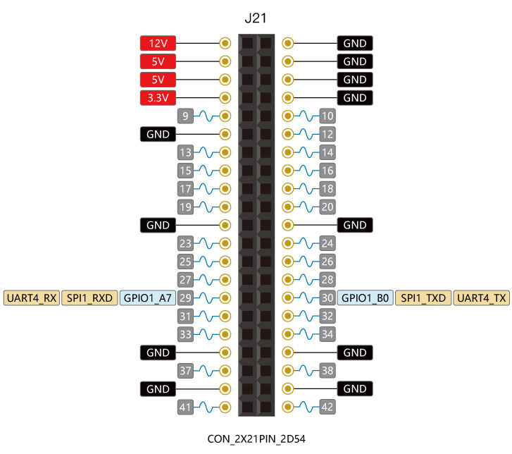
GPIO1_A7 and GPIO1_B0 can be reused as uart4_rx and uart4_tx,
DTS Config
The file kernel/arch/arm64/boot/dts/rockchip/rk3399.dtsi has the definition of UART nodes:
   aliases {
       ...
       serial0 = &uart0;
       serial1 = &uart1;
       serial2 = &uart2;
       serial3 = &uart3;
       serial4 = &uart4;
   };
serial0 is defined in aliases node as: serial3 = &uart0;.
Because our Firefly-RK3399 development board opens the uart4 for the user to use,using uart4 as an example to introduce the use of the serial port. The following are the uart4 node-related definitions:
   uart4: serial@ff370000 {
       compatible = "rockchip,rk3399-uart", "snps,dw-apb-uart";
       reg = <0x0 0xff370000 0x0 0x100>;
       clocks = <&pmucru SCLK_UART4_PMU>, <&pmucru PCLK_UART4_PMU>;
       clock-names = "baudclk", "apb_pclk";
       interrupts = <GIC_SPI 102 IRQ_TYPE_LEVEL_HIGH 0>;
       reg-shift = <2>;
       reg-io-width = <4>;
       pinctrl-names = "default";
       pinctrl-0 = <&uart4_xfer>;
       status = "disabled";
   };
   uart4 {
       uart4_xfer: uart4-xfer {
       rockchip,pins =
               <1 7 RK_FUNC_1 &pcfg_pull_up>,
               <1 8 RK_FUNC_1 &pcfg_pull_none>;
       };
   };
You only need to enable the node in the kernel/arch/arm64/boot/dts/rockchip/rk3399-firefly-port.dtsi file,as follows:
&uart4 {
       current-speed = <9600>;
       no-loopback-test;
       status = "okay";
};
uart_rx and uart_tx can be reused as spi1_rxd and spi1_txd, so be careful to shut down the use of SPI1, as follows:
&spidev0 {
	status = "disabled";
};
Debugging method
You can now communicate with the uart4 via a USB-to-serial adapter in your host PC. Follow the steps below:
(1) Connect the uart port.
Connect the TX, RX, GND pins of uart4 to the serial adapter's TX, RX, GND pins respectively.
(2) Open a serial terminal in host PC.
Run kermit in a shell window, and set baud rate:
$ sudo kermit
C-Kermit> set line /dev/ttyUSB0
C-Kermit> set speed 9600
C-Kermit> set flow-control none
C-Kermit> connect/dev/ttyUSB0is the device file of USB-to-serial adapter.- baud is the
current-speedattribute in the DTS node.
(3) Transmit data.
The device file for uart4 is /dev/ttyS4. Run the following command in device:
echo firefly uart4 test... > /dev/ttyS4The serial terminal in the host PC will receive string firefly uart4 test....
(4) Receive data
First, run the following command in device:
cat /dev/ttyS4Then input string Firefly uart4 test... in the serial terminal.You can see the same string received in the device.
FAQs
Q1: Why is the system error after connecting to the serial adapter?
A1: Firefly RK3399 development board's TX and RX, respectively, corresponding to the serial port adapter's TX and RX, If confused, it will lead to serial communication error.