

RK1828 Multi-Card Cascade: Deploying a 27B LLM at the Edge
RK1828 Multi-Card Cascade: Deploying a 27B LLM at the Edge
Technical Motivation for Multi-Card Cascade
Two Constraints of Edge Inference
| Constraint | Manifestation | Direct consequence |
|---|---|---|
| Memory capacity | A single card cannot hold all weights of a large model | Large-parameter models cannot be deployed on one card |
| Compute throughput | Single-card throughput cannot sustain continuous decoding | Even if the model loads, throughput cannot meet interactive requirements |
The multi-card cascade path is straightforward: aggregate the memory and compute of multiple cards and schedule them as a single logical accelerator.
Model Partitionability
A Transformer is a stack of structurally identical decoder layers. Layers are connected head-to-tail, and each layer's parameters are independent of the others. It follows that:
- Once the first several layers finish computing, their output can be handed directly to another chip holding the weights of the subsequent layers
- No structural pruning of the original weights is required — after partitioning and recombination, the model remains the complete original model
Overall Architecture and Hardware Form Factor
The host side takes on the orchestration role: tokenization and embedding mapping, device discovery, segment scheduling, and Logits sampling for the final segment. Each card only executes the decoder-layer computation of its own segment, and passes intermediate features (hidden states) to the next segment.
Hardware Form Factor and Connection Options
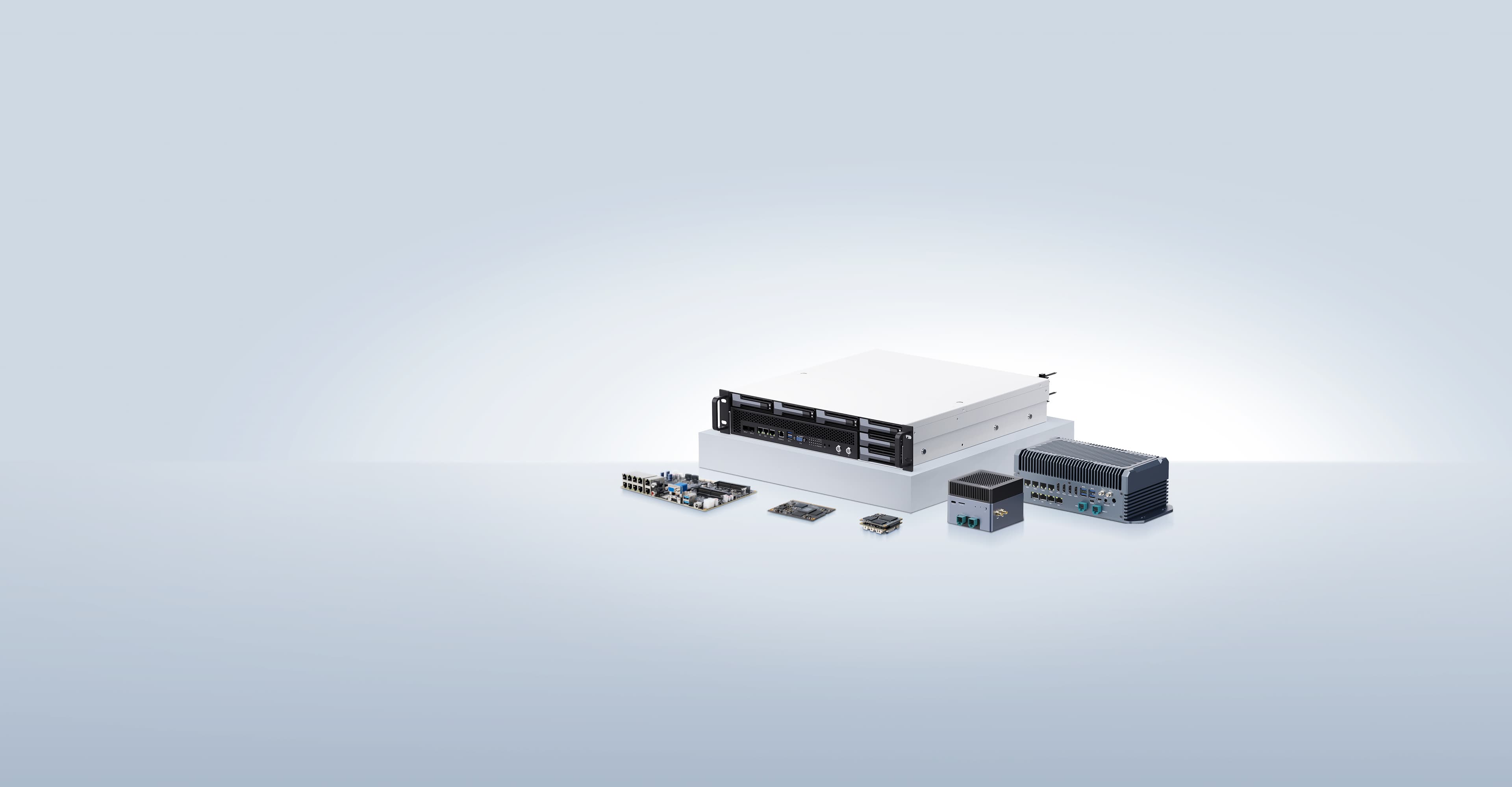
The RK1828 is an NPU compute card in SO-DIMM form factor. Three connection options are officially provided:
| Connection | Structure | Characteristics |
|---|---|---|
| Dedicated PCIe direct | Each card occupies its own PCIe 2.0 x1 lane | Independent links, no shared contention |
| PCIe switch expansion | Upstream PCIe 2.0 x1 or PCIe 3.0 x4, distributed to 2/4 cards via a switch | Saves host interface resources |
| USB3.0 hub expansion | 4 cards share a single USB3.0 hub | Fast to integrate, suitable for quick validation |
The three options have limited performance impact: per Rockchip's official testing, under 4K / 8K input, PCIe holds roughly a 2%–3% advantage over USB3.0 in TTFT and Prefill, while the two are essentially equivalent in the Decode stage.
Besides the SO-DIMM form factor, the RK1828 is also available as an M.2 Key B-M version.
Supported Host Platforms
- ARM64 platforms: RK3588, RK3576, and others, with Linux and Android support
- Windows x86 platforms
- Reuses the RKNN3 Runtime and application interfaces — no re-adaptation of the upper-layer application is required
Configuration and Model Scale
| Configuration | Adapted models | Typical use |
|---|---|---|
| 2 cards | Qwen3.5-9B (2 segments) | Lightweight chat, multimodal understanding, local speech processing |
| 4 cards | Qwen3.8-27B (4 segments) | Large-parameter Chinese models, coding agents, local knowledge Q&A |
Core Principle: Inter-Layer Pipeline Parallelism
Model Segmenting
Segmenting divides the model contiguously in units of decoder layers. Taking the Qwen3.5-9B (32 layers) dual-card solution as an example:
| Segment | Loaded on | Responsibility |
|---|---|---|
| Segment 0 | Card 0 | Layers 0–18, 19 decoder layers in total |
| Segment 1 | Card 1 | Layers 19–31, 13 decoder layers + Final Norm + LM Head |
As shown, the split is not even (19 / 13); it is determined by RKNN3-Toolkit after balancing quantized weight and memory footprint. The final segment additionally carries the Final Norm and LM Head. The complete inference chain is:
Host tokenization / embeddings → Card 0 front segment compute → intermediate feature transfer → Card 1 back segment + output head → Logits → Host samplingThe four-card solution works the same way, simply with more intermediate segments.
Serial Execution: Data Dependencies Determine Execution Order
The key to understanding this solution is the inter-card data transfer mechanism. What is passed between segments is the intermediate feature (hidden states) plus that segment's KV cache, and the input of segment N+1 is exactly the output of segment N — without input there is nothing to compute, so a later segment must wait for the previous one to finish.
For any single token, only one segment is computing at any given moment. This is not a scheduling choice but a necessary consequence of data dependencies. The process can be compared to data flowing through a multi-stage cascaded filter chain: each stage performs only its own portion of the computation, its output serving as the next stage's input, and there is no case where multiple stages process the same sample simultaneously.
Two implementation details are worth noting:
- Intermediate features are currently transferred via the host side; direct card-to-card links are still under development
- The solution requires
stage_count = number of segments, and available devices ≥ number of segments — otherwise a complete inference pass cannot be performed
Prefill Pipeline: Bucket Splitting and Queue-Based Parallelism
This is the key optimization of the solution in long-input scenarios, and it corrects the intuitive impression that "prefill can only be purely serial."
In practice, a long input does not flow through all segments serially as one whole; instead it is split into buckets, with the segments' execution queues running in parallel:
| Stage | Bucket 0 | Bucket 1 | Bucket 2 |
|---|---|---|---|
| Time slice 1 | S0 | — | — |
| Time slice 2 | S1 | S0 | — |
| Time slice 3 | SN | S1 | S0 |
That is, once Bucket 0 enters segment 1, Bucket 1 can already start computing on segment 0. In this way, each segment stays busy in long-prompt scenarios, and prefill throughput rises substantially — the Qwen3.8-27B four-card solution reaches a Prefill throughput of 592.1 tokens/s, far above its decode throughput of 13 tokens/s.
The Decode stage is different: because there is only one token per round, it cannot be split into buckets, and the segments sit in a "hand off one by one, take turns working" state, so pipeline utilization is inherently low. This is the root cause of the order-of-magnitude throughput gap between the two stages.
Comparison with Tensor Parallelism
| Aspect | Inter-layer pipeline parallelism (this solution) | Tensor parallelism |
|---|---|---|
| Unit of partitioning | Split by decoder layer | Split by matrix shard |
| Inter-card collaboration | Serial transfer of intermediate features | Parallel compute + reduction |
| Inter-card communication volume | One transfer per segment boundary | Multiple high-frequency syncs within each layer |
| Interconnect bandwidth requirement | PCIe 2.0 x1 / USB3.0 acceptable | Very high (NVLink-class) |
| Edge feasibility | Feasible | Limited by PCIe / M.2 bandwidth |
Choosing inter-layer pipeline parallelism at the edge is essentially an engineering trade-off under constrained inter-card bandwidth.
TTFT and TPOT: Analysis of Performance Metrics
Causes of Time To First Token (TTFT)
It results from two compounding factors.
Factor 1: The model must first complete encoding of the entire input. A Transformer generates autoregressively, so the first output token can only be predicted after attention has been computed over all input tokens. Each attention layer depends on the complete output of the previous layer, forming a serial dependency chain across layers.
Analogous to: to answer a question about a document thousands of lines long, the document must first be read in full. The time spent "reading" corresponds to the prefill stage.
Factor 2: The input encoding process is divided into a multi-station pipeline, and grows linearly with input length. Total prefill time ≈ the sum of per-segment compute time and inter-card transfer time. Hence TTFT is approximately proportional to input length (the table below uses official test data):
| Configuration | 4K input | 8K input | Ratio |
|---|---|---|---|
| Qwen3.5-9B · 2 cards · PCIe | 4.80s | 9.73s | ≈ 2.03 |
| Qwen3.8-27B · 4 cards · PCIe | 6.92s | 13.67s | ≈ 1.98 |
Doubling the input length nearly doubles TTFT — indicating that prefill time is spent mainly on processing input tokens rather than on fixed overhead.
Causes of Time Per Output Token (TPOT)
The key lies in the KV cache. The key-value caches computed by each card during prefill are retained in local memory. From then on, each decode round:
- Only a single new token (the previous round's output) needs to enter the pipeline; the full input does not need to be recomputed
- Each card performs incremental computation using the new token and the cached KV
- It still passes through all segments, but each segment handles only a single token's worth of computation
Unit-Cost Comparison
| Stage | Unit cost (Qwen3.8-27B · 4 cards · 4K input, official data) | Bottleneck nature |
|---|---|---|
| Prefill | 592.1 tokens/s ≈ 1.69ms/token | Compute-bound — bucket queue parallelism keeps NPU utilization high |
| Decode | 13.02 tokens/s ≈ 76.8ms/token | Memory-bound — each step must re-read every card's weights |
In terms of per-token processing cost, prefill is more than 40× cheaper than decode. This also explains a common engineering optimization: the same long system prompt responds noticeably faster on the second query, because the KV cache can be reused directly and prefill need not be re-run (prefix caching / prompt cache).
The conclusion can be summarized as:
The high TTFT stems from the compounding of "full input encoding" and "serial transfer across segments," and grows linearly with input length; the per-token latency in the decode stage is mainly limited by memory bandwidth.
Software Stack: The Full Chain from Application Entry to NPU
Layer 1 · Application   Browser / OpenAI SDK / OpenCode
        ↓
Layer 2 · API           Local Web UI / OpenAI-compatible API
        ↓
Layer 3 · Server        RKLLM3 Server / Agent orchestration
        ↓
Layer 4 · Runtime       RKNN3 Runtime
        ↓
Layer 5 · Hardware      RK1828 NPU compute card × N

Requests flow top-down; results return in the opposite direction as streamed tokens| Layer | Responsibility | Typical entry point |
|---|---|---|
| Application | User / business system interaction | Browser / OpenAI SDK / OpenCode |
| API | Provides a standardized inference interface | Local Web UI / OpenAI-compatible API |
| Server | Model serving and agent orchestration | RKLLM3 Server / Agent applications |
| Runtime | Model inference runtime | RKNN3 Runtime |
| Hardware | Edge NPU acceleration | RK1828 NPU compute card |
Performance Data
Test conditions: RK3588 host · RK1828 SO-DIMM · W4A16 quantization · output fixed at 128 tokens (Rockchip official testing)
| Model | Accelerator | Input | Interface | TTFT (s) | Prefill TPS | Decode TPS |
|---|---|---|---|---|---|---|
| Qwen3.5-9B | 2× RK1828 | 4K | PCIe | 4.80 | 853.7 | 33.19 |
| Qwen3.5-9B | 2× RK1828 | 4K | USB3.0 | 4.90 | 836.0 | 33.52 |
| Qwen3.5-9B | 2× RK1828 | 8K | PCIe | 9.73 | 841.7 | 32.33 |
| Qwen3.5-9B | 2× RK1828 | 8K | USB3.0 | 9.94 | 824.0 | 32.65 |
| Qwen3.8-27B | 4× RK1828 | 4K | PCIe | 6.92 | 592.1 | 13.02 |
| Qwen3.8-27B | 4× RK1828 | 4K | USB3.0 | 7.15 | 573.2 | 13.02 |
| Qwen3.8-27B | 4× RK1828 | 8K | PCIe | 13.67 | 599.4 | 12.74 |
| Qwen3.8-27B | 4× RK1828 | 8K | USB3.0 | 14.08 | 581.7 | 12.83 |
Note: In official testing, the PCIe interface holds roughly a 2%–3% advantage over USB3.0 in TTFT and Prefill.
Metric Definitions
| Metric | Meaning | Stage |
|---|---|---|
| TTFT | Time To First Token — latency from submitting input to emitting the first token | Covers prefill |
| Prefill TPS | Token processing throughput during the input stage | Prefill |
| Decode TPS | Tokens generated per second during the output stage = 1000 ÷ TPOT | Decode |
Reading the Data
1. Doubling the parameter scale causes a marked throughput drop. Qwen3.5-9B on two cards reaches 33.19 tokens/s in decode, while Qwen3.8-27B on four cards falls to 13.02 tokens/s. Both the parameter count and the segment count increase, so each token must traverse more serial computation and transfer. Cascade solves a capacity problem, not a throughput problem.
2. Input length is the dominant factor for TTFT. With the same 4-card configuration, going from 4K to 8K input raises TTFT from 6.92s to 13.67s, while decode throughput is essentially unchanged (13.02 → 12.74). This confirms that the prefill and decode stages have entirely different bottleneck characteristics.
3. Interface differences are visible in prefill, invisible in decode. The TTFT gap between PCIe and USB3.0 is stable at 2%–3%, while decode TPS is identical for both (13.02). The reason is that the amount of data transferred per decode round is very small, so the bottleneck lies in weight reads rather than link bandwidth.
4. Prefill throughput declines with card count, but far less than decode. 9B on two cards: 853.7 → 27B on four cards: 592.1 (down about 31%), while decode drops from 33.19 to 13.02 (down about 61%). This is consistent with the bucket pipeline mechanism described above — the prefill pipeline can be filled by multiple buckets, whereas the decode stage cannot.
Resource Usage and System Power
Beyond performance metrics, host-side resource usage and overall system power are equally critical constraints for edge deployment.
Host System Overhead
Test conditions: RK3588 host · RK1828 SO-DIMM, with 4× A76 cores at full load as the 100% baseline (Rockchip official data)
| Configuration | Interface | Avg. CPU usage | Avg. memory | Peak memory |
|---|---|---|---|---|
| Qwen3.5-9B · 2 cards | PCIe | 2.4% | 179 MB | 310 MB |
| Qwen3.5-9B · 2 cards | USB3.0 | 2.0% | 181 MB | 312 MB |
| Qwen3.8-27B · 4 cards | PCIe | 2.6% | 191 MB | 524 MB |
| Qwen3.8-27B · 4 cards | USB3.0 | 2.2% | 187 MB | 523 MB |
Host CPU usage stays under 3% and memory usage is in the hundreds of MB — indicating that the host barely participates in actual inference computation and mainly handles orchestration and scheduling, with the compute load entirely offloaded to the compute cards.
System Power Consumption
Test conditions: RK3588 host · 4× RK1828 SO-DIMM, whole-system validation (including cooling fan) (Rockchip official data)
| Configuration | Interface | Input | Avg. system power | Peak system power |
|---|---|---|---|---|
| Qwen3.5-9B · 2 cards | PCIe | 8K | 30.5 W | 67 W |
| Qwen3.8-27B · 4 cards | PCIe | 8K | 57.8 W | 119 W |
Divided by card count, the per-card power is on the order of about 15W (average), comparable to typical edge compute cards. For power-sensitive devices (battery-powered, in-vehicle, robot body), this magnitude must be factored into the whole-system power budget: the peak power of the 27B four-card solution approaches 120W, exceeding the supply capability of most small mobile platforms.